
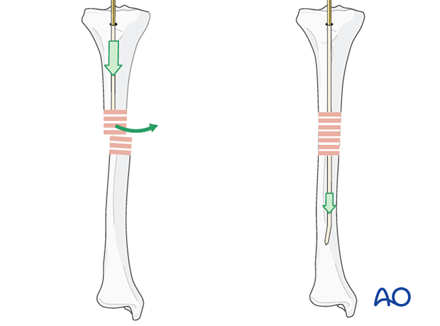
Intramedullary nailing Basic technique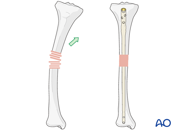 1. Introduction An intramedullary (IM) nail provides the strongest mechanical fixation of any shaft fracture. There may be practical reasons (eg, existing hardware or a small intramedullary canal) or biological reasons (eg, soft tissue concerns) why other methods would be chosen. Nailing may be performed antegrade (proximal to distal) or retrograde (distal to proximal). Angular stability A shaft fracture may be displaced in a variety of ways. An IM nail restores axial alignment and prevents angulation.
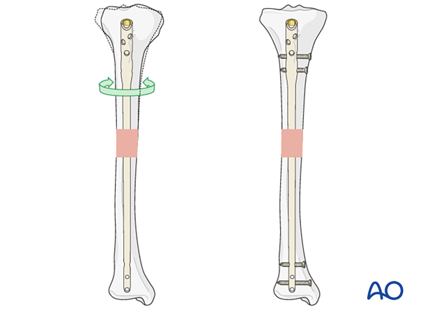
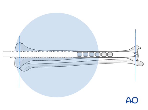
Rotational stability Without locking, an IM nail may not provide rotational control. The fracture plane or interdigitation of the fragments may provide some rotational control, but it is usually more reliable to use proximal and distal locking, as shown in the image on the right.
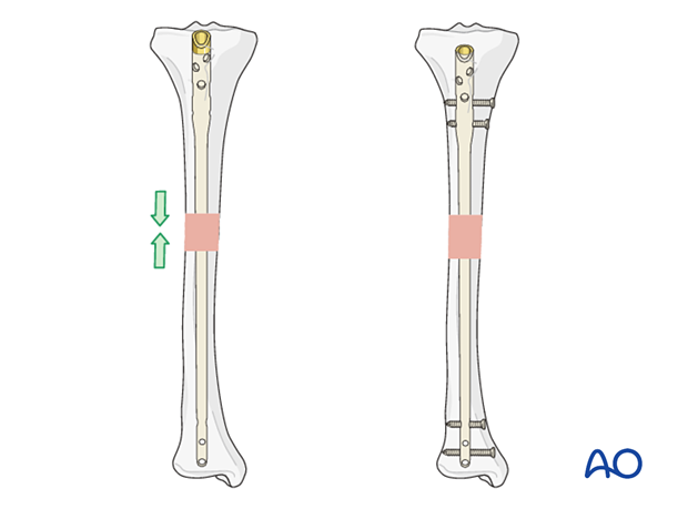
Longitudinal stability (shortening) Multifragmentary fractures are not length stable. Therefore, proximal and distal locking screws must be used.
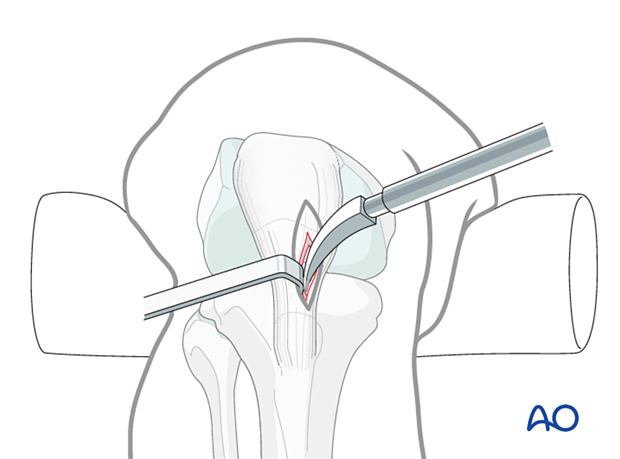
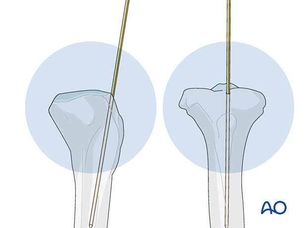
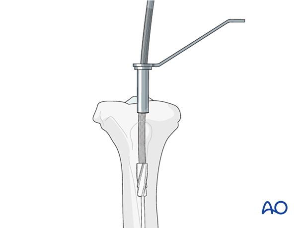
2. Nail entry point The ideal entry point depends on nail design, and the bone that is to be fixed. The entry point can be estimated from x-rays by extrapolating the axis of the medullary canal. Once the entry point has been chosen, it is opened with an awl or a drill. In some systems, these may be cannulated.
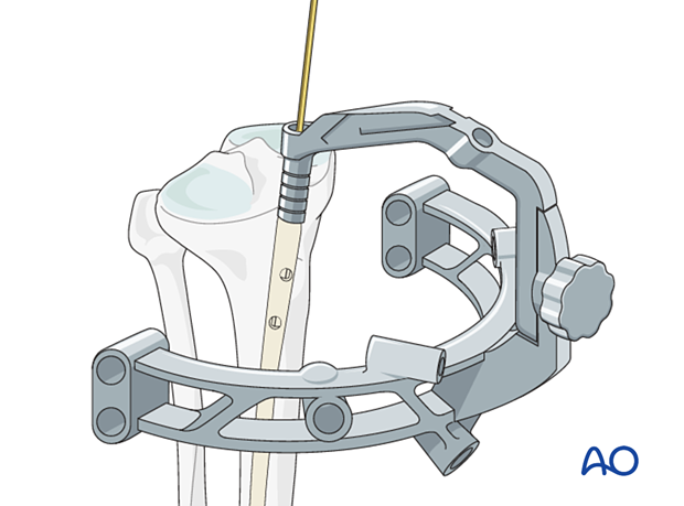
3. Insertion of guide wires Most IM nails are inserted over a guide wire. Reaming is always performed over a guide wire. The guide wire is inserted under x-ray control.
In order to facilitate passing the guide wire across the fracture site, the fracture should be adequately aligned. It may be easier to pass the guide wire
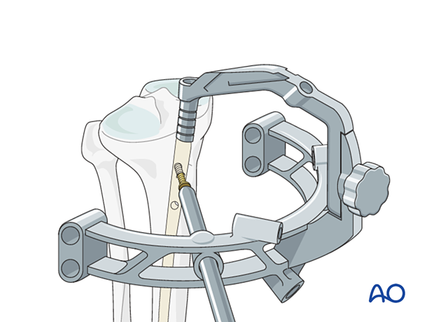
If the fracture ends cannot be sufficiently aligned for a guide wire to be passed, Alternatively, percutaneous reduction aids, eg, a Schanz pin with T-handle, ball-spiked pusher, bone hook, or F-tool, can be used. In some cases, there may be soft-tissue interposition which prevents reduction. This may require open reduction.
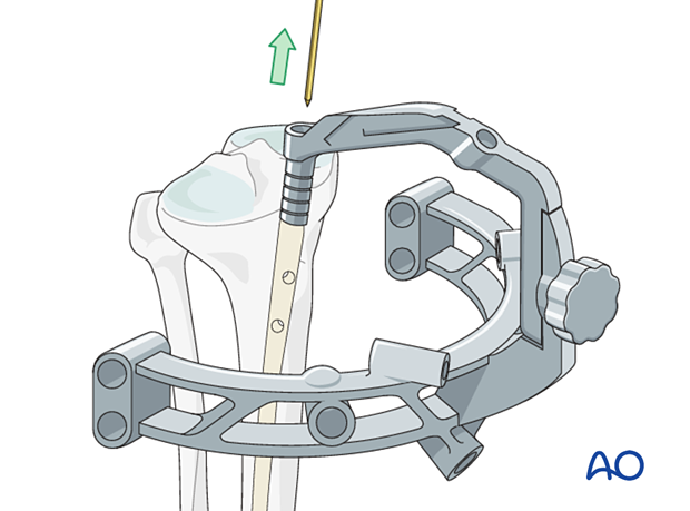
An olive-tipped guide wire is used during reaming, so that the reamer head may be extracted if the driveshaft breaks.
4. Reaming If the medullary canal is narrow, it may be necessary to enlarge it by reaming to allow the insertion of a larger diameter nail with sufficient strength. Reaming also increases the area of contact between the nail and the endosteal surface of the bone at the isthmus. Although reaming damages the endosteal blood flow, which returns several weeks after surgery, the periosteal blood supply is sufficient for early fracture healing. The position of the reamer can be checked intermittently under x-ray control. Reaming generates heat, particularly if reamers are blunt, so it is important not to apply excessive force whilst reaming. (If used, a tourniquet should be deflated when tibial reaming is performed The first reamer heads used have a small diameter, and
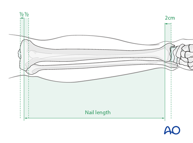
5. Determination of nail length and diameter Preoperative planning is essential. In multifragmentary fractures, or in open fractures with bone loss, the uninjured leg can be used as a guide during preoperative planning to help select an appropriate nail. In bilateral fractures, the less comminuted side should be used to determine the length and diameter of the nail.
Determination of length using a depth gauge All intramedullary nailing sets come with a depth gauge that is slid over the guide wire to determine the length of the nail to be inserted. X-ray imaging is used to confirm proper length. If there are issues with using the depth gauge, alternative techniques to determine nail length are described below.
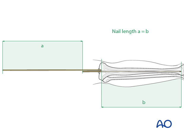
Determination of length using a second guide wire The correct length of the nail can be determined by comparing a second guide wire of the same length to the one that has been inserted. The correct placement of the guide wire in the distal canal should be assessed via image intensifier. The tip of the second guide wire must be positioned at the entry point in the bone. Measure the difference in length between the two wires (a). This difference represents the proper nail length (b), see illustration. It is always advisable to double-check the measured length by comparison with the uninjured leg.
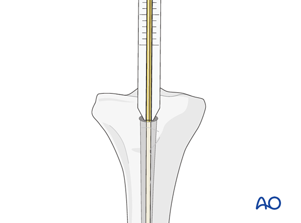
Determination of length using a radiographic ruler Alternatively, a radiographic ruler may be used. The tip of the ruler should be positioned where the tip of the nail is intended to lie. Nail length is determined by the position of the nail entry point.
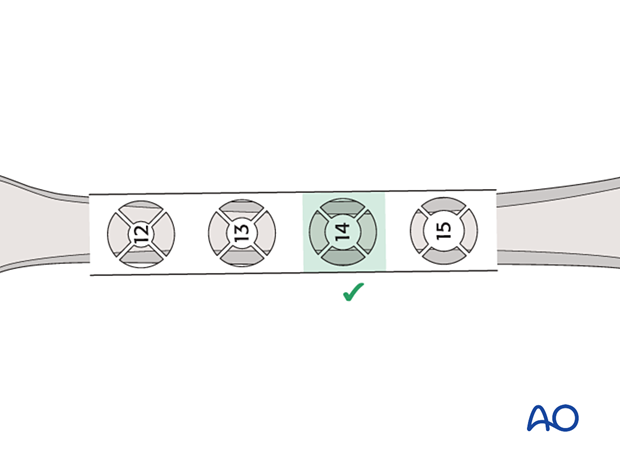
Determination of diameter Nail diameter may be determined from the size of the last reamer used. The nail diameter is typically 1–1.5 mm smaller than the largest reamer used. Alternatively, a radiographic ruler may be used. It is important to measure the medullary diameter at the mid portion of the bone, which represents the narrowest segment of the medullary canal. The inner cortical edge should touch the inner numbered disk of the ruler aperture. In the illustration an inner cortical diameter of 14 mm is shown. In this case, a 12.5 mm or 13 mm nail would be used.
6. Nail insertion It may be necessary to exchange the olive-tipped guide wire for a straight guide wire in order to pass the nail through the medullary canal. An appropriately sized nail is mounted on the introduction handle, which normally incorporates the guides for proximal locking. If the nailing system has different implants for left and right sides, ensure the correct implant is selected, and the introducer is assembled correctly to ensure proper positioning of the nail.
If a guide wire is used, slide the nail over the guide wire and introduce it into the bone. Ideally the nail can be pushed down with twisting movements, but in practice some hammering may be needed. The nail is inserted under x-ray control, with particular care being taken as the tip of the nail passes through the fracture site. Care must be taken not to create a fracture, particularly in osteoporotic bone.
Make sure the nail is fully seated in the planned position. Depending on the bone and the nail, the position may be determined by the planned screw insertion, eg, into the femoral or humeral head. In general, the top of the nail should be flush with the surface of the bone, or should lie just under the surface.
Pearl: When performing prophylactic nailing in patients with impending pathological fractures, particular care must be taken when inserting the nail as the bone may be more curved than the nail which is being inserted. This may result in an iatrogenic fracture at the site of the metastasis, or the tip of the nail may protrude through the cortex distally. This risk may be reduced by increasing the difference in size between the last reamer and the nail diameter. 7. Locking The guide wire must be removed before locking can be started.
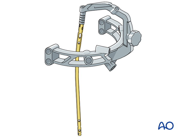
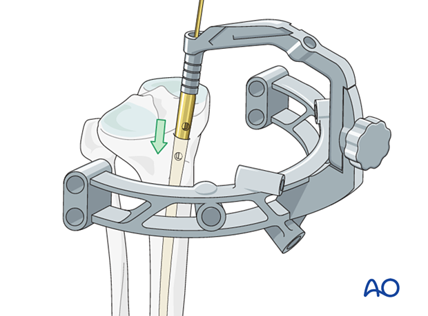
Proximal locking Proximal locking is normally performed using a guide attached to the nail.
Distal locking As the nail has a tendency to deform slightly as it is inserted, guides attached to the proximal end are not accurate enough for distal locking. Distal locking is usually performed under x-ray control.
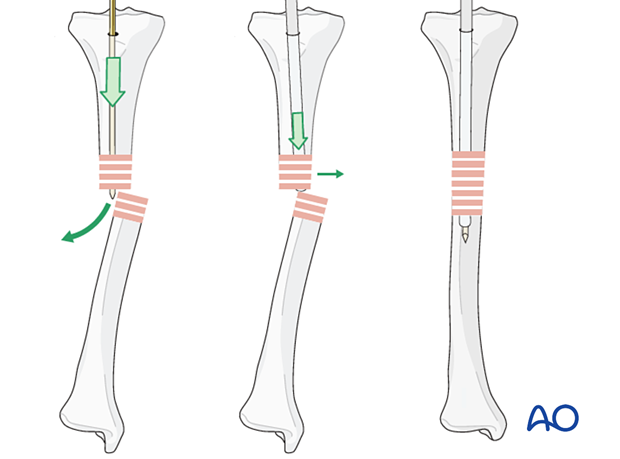
Displacement In more proximal or distal fractures, as the metaphysis does not provide much support for the nail, there is a tendency for angular displacement.
If only parallel screws are used for locking, a small metaphyseal segment may still displace along the screw axis.
Screws should therefore be inserted in different axes, if the design of the nail allows.
Alternatively, blocking screws (Poller screws) may be used adjacent to the nail. The position of the blocking screws is dictated by the anticipated direction of displacement, which can be predicted from the fracture configuration.
8. Nail cap Most modern nailing systems have nail caps. These help to reduce bony ingrowth into the nail. If the top of the nail is seated well below the surface of the bone, a longer nail cap should be used if available. This will mean that less bone needs to be cut away to uncover the nail cap if the nail is subsequently removed.
9. Nail removal It is generally not necessary to remove IM nails unless patients are symptomatic. Unless there is an indication for urgent removal of the nail, it should not be removed until the fracture has definitely united. Remove any bone that has grown over the top of the nail with an osteotome. It may be helpful to have imaging available for this procedure.
The nail cap is removed prior to attachment of the extraction device.
The extraction device should be attached, before removing the locking screws.
The locking screws are then removed and the nail extracted.
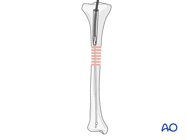
10. Removal of broken nail Various techniques have been developed that allow the removal of broken nails with specialized instruments. If such instruments are not available, the following simple technique can be employed using guide wires. If the nail is hollow, remove all locking screws but do not remove the proximal fragment.
It should be possible to pass an olive-tipped guide wire down to and through the nail tip.
One or more straight guide wires are then also passed out through the tip of the nail. This should block the olive, preventing it from reentering the nail. Some trial and error may be needed to determine the correct size of olive.
Once the olive is blocked, a T-handle chuck may be attached to the olive-tipped guide wire and the nail backed out using a hammer.
|


Shanghai Carefix Medical Instrument Co., Ltd.China
沪ICP备16042301号-1 (沪)-非经营性-2016-0122 沪食药监械生产许20101725号